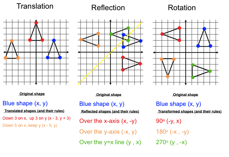

This enables you to foresee the design challenges and make the required tweaks to achieve the desired board functionality. A Reflection Calculator is used to find a points inversion. Sierra Circuits’ Transmission Line Reflection Calculator will greatly help you to understand the signal characteristics during the design phase. A screen pops up displaying the voltage at the input and output of the transmission line.Ī transmission line should have a uniform characteristic impedance to avoid signal reflections. Line Of Reflection CalculatorAuto Flip Flip Snap to grid Select Reflection Line Back to Transformations Next to Reflections Lesson. To view these values, click on Show Calculations. The tool calculates the incident voltage (V i), reflected voltage (V rl), and the output voltage (V o) at the source and the load for different time intervals based on the input. Signal reflection at input and output end The signal reflections at the input and output ends of the transmission line are represented by red and green curves, respectively. Once the values of these parameters are entered, hit Calculate to view the voltage versus time graph. You can click on help ( ?) to learn more about these. In the input section, provide the following data: The Transmission Line Reflection Calculator has 2 sections: Input and Output Sierra Circuits Transmission Line Reflection Calculator will greatly help.
#LINE OF REFLECTION CALCULATOR HOW TO#
How to use the Transmission Line Reflection Calculator Transmission Line Reflection Calculator Interactive, free online graphing calculator from GeoGebra: graph functions. Auto Flip Flip Snap to grid Select Reflection Line Back to.

This tool graphically depicts the ringing of a signal at the source and load of a transmission line. Free functions composition calculator - solve functions compositions step-by-step A function. These reflections are referred to as ringing. The reflected signal propagates in the direction opposite to the main signal. Any discontinuity at any point will affect the uniformity of the characteristic impedance and cause reflections. The characteristic impedance of a PCB trace should remain constant to have a uniform transmission line.


 0 kommentar(er)
